Key Concepts, Terms, and Equations for Using FracLac for ImageJ
This glossary is arranged alphabetically by key terms. Each term lists synonyms and offers links to related entries and the relevant pages in this manual. Search using your brower's "Find" function to locate a specific term or click on one of the categories to the right.
- Fractal Dimension (DB Box Counting)
- DB
- Box Counting Dimension
- DB
- a fractal dimension (DF) useful for objectively quantifying complexity in digital images.
- A scaling rule for the relationship between count and box size in box counting, assuming these correspond respectively to detail (or N, the number of parts) and scale (ε) according to the equation:
DB=limε→0[log Nε⁄log ε]
where the limit is found as the slope of the regression line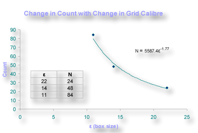
- Types of DB FracLac Calculates:
- fractal
- monofractal
- scaling rule
- scale
- dimension
- scale
- Scaling rule is similar to dimension. Informally, think of it like this: an ordinary square is considered 2-dimensional—it has a dimension of 2. If you measure it using another square half its size (i.e., we divide the original side by 2, naming the scaling factor S and letting S = 2), you will find it's measure (N) to be 4 such new squares. The dimension or scaling rule is found from N = SD: 4 = 2D, where we see that D is 2. Do the same with an ordinary 1-d line. If you measure the line using pieces 1/3 the original length, you would get 3 new pieces. In this case, S = 3 and N = 3 so 3 = 3D such that D = 1. For a 3-d cube, if S = 2, N = 8, so 8 = 2D and D = 3. In general, N = SD, where we call D the dimension or scaling rule.
- A fractal pattern is one that has a scaling rule or dimension that may be a fraction. A fractal pattern scales infinitely to reproduce itself such that traditional geometry does not define it. In particular, when you scale a fractal line or divide it by a number, S, you do not get N = S pieces, each 1/S the size of the original. Instead, the "scaling rule" or fractal dimension, DF, for the pattern is defined by the values you do get when you scale the pattern, according to the general relationship N = SD, where N is the number of so-called "self-similar" parts, meaning the parts reiterate the essence of the original.
- D can be solved using logs: D = log N/log S; alternatively,
fractals are often discussed using a relative scale (e.g., R = 1/S), where -D = log N/log R. The mathematical basis of fractals and scaling is discussed in the Fractals and Fractal Dimension pages in the Background Section of this manual.
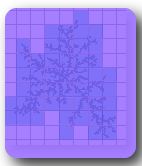
See an example of a 32-segment quadric fractal highlighting the basic self-similar nature of a fractal here.
You may also wish to read about the DF and DB and multifractals
- Fractional Dimension
- DF
- DF
- D
- an index of how detail changes with resolution, based on the notion of dimension arising from N = R-D, where N is some number of counted constituent parts of a pattern and R is the relative scale at which the number of parts was measured.
- a measure of complexity calculated as:
DF = log N ε/log ε
and approximated as the slope of the reqression line from:
where N=the number of new parts and ε is the scaleD = limε→0 [log Nε⁄log ε]
- the DB is a fractal dimension
- Complex
- change in detail
- complexity in this manual is the basis of the fractal dimension; it refers to a change in detail or the number of parts something is made up of, with change in scale (in microscopy, the change in scale is the change in magnification or resolution); click the image to learn more

- Box Counting
- box counting
- the main data gathering method in FracLac
- laying grids on a digital image and counting the boxes that contained foreground pixels and the pixels per box to determine the DB and lacunarity
- Count
- Pixel Count
- Box Count
- Number of Boxes
- Boxes containing foreground pixels
- Boxes at Epsilon
- the number of sampling elements (i.e., boxes or ovals) at a particular box size that contained meaningful foreground pixels in a box counting scan
- the count is used along with size or scale in calculating the DB
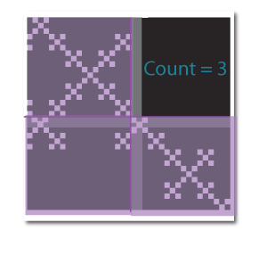
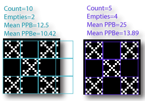
- The image below illustrates the idea for a regular box count - the count at the size shown is 3, because three boxes contained white pixels on a black background, and the fourth was empty
- inferring a scaling rule from box counting requires, as you might expect, a "box count", but what is actually considered in the calculations differs in some scans (e.g., the "mass" or number of pixels per box is considered in mass, lacunarity, multifractal, and other scans; in grayscale scans, the thing counted relates to average pixel intensity; and in local connected fractal dimension scans, the count is determined using a different method than in regular box counting)
- Box Size
- Caliber
- Calibre
- Grid Calibre
- Grid Size
- Size of the Sampling Element
- Sampling Element
- the diameter, usually specified in pixels, of the individual boxes or ovals used to sample an object with box counting
- In FracLac, sizes of boxes are calculated based on user settings for each scan type
- the length of the side of the squares making up the grid that a user sets in regular box counting and multifractal analysis
- the length of the side of the square a user sets for a sliding scan
- In local connected fractal dimension analysis and mass vs distance analysis, the diameter of the sampling unit, square or round; this should be an odd number for proper sampling; otherwise the samples will not be concentric
- used for scale and along with count in calculating the fractal dimension

Calculating the DB
epsilon
example
setting the series of grid sizes
Reporting the sizes used in a scan
- Scale
- scale
- epsilon
- ε
- the scale applied to an object in fractal analysis
- is intimately related to detail or the "number of parts" something can be perceived as being composed of (count) in calculating the fractal dimension
- the resolution or magnification at which something is viewed
- In FracLac, ε is box size relative to image size and is used in calculating the fractal dimension
- the number of times something is changed in size relative to itself; e.g., a 100 cm line scaled by 1/4 becomes 25 cm long
ε = box size/image size
- Grid
- Sampling Grid
- Scanning Element
- the boxes - the rectangular array that an image is broken into for box counting
- can be considered as several regular squares
- in nonverlapping scans, the scanning element is a fixed grid of boxes, but in sliding scans, the scanning element is a single box
- the actual sampling unit may be an oval or a rectangle, depending on the user's choices, but the sampling in box counting is done in a rectangular array
Grid Position
Box Size or Grid Size
Overlapping Scans
Nonoverlapping Scans
Example image showing different grids laid on a pattern
- Grid Position
- Grid Position
- Grid Location
- Sampling Grid Orientation
- Number of Grids
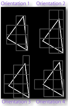
- the orientation of a grid with respect to an image; or where the grid is placed on an image in a box count, as in the illustration
- affects the count and depends on the type of scan selected and several user options for each scan
- for the selected number of grid positions, one series of grids including all box sizes is placed at the starting location for each orientation, and pixels are counted.
- the actual grid orientations used are reported in the data and results files
- for a standard box count scan, the first 4 grids's orientations are the corners of the bounding box of the foreground pixels or image, then FracLac determines all other orientations using a list of predetermined random numbers that generates x,y coordinates around those 4 starting locations, within an area the size of the biggest box in the series of grid calibres.
- multiple grid positions are used to calculate the mean DB, and minimum cover DB.
Example image of changing grid location
mean and Minimum Cover DB
Grid Position for Multifractal Analysis
overlapping grids
- Fractal Dimension (DΛ Pixel-mass Lacunarity)
- ΛDB
- lacunarity based DB
- a fractal dimension calculated from pixel mass lacunarity
- It is calculated: ΛDg=(limε→0[lnσ(ε)⁄lnε])-((limε→0[lnλ(ε)⁄lnε])/2)
- where
- limε→0 is found as the slope of the regression line
- g is grid orientation; ε is scale; σ is the standard deviation and μ the mean for pixels per box at some ε
- λ=(σ/μ)2
- if averaged over all locations = ΛDB= [Grids∑G=1(ΛDB(G))]×Grids-1
- Fractal Dimension (DM Mass)
- Mass Dimension
- DBmass
- Mass DF
- the DB calculated using pixels per box
- DBmass= limε→0[ln με ⁄ln ε]
- limε→0 is found as the slope of the regression line for με and ε
- με = the mean pixels per box at some ε, where ε = box size or scale
- a mass dimension for each grid series is reported in the Data File
- the LCFD is a mass dimension
- the binned probability Dm orBPDDm is a mass dimension
- Scan (Global Scan)
- Global Scan
- global dimension
- a box counting scan that goes over an entire image or ROI and summarizes the scan with one number, as opposed to local scans.
- global scans may be done using multiple grid positions, where the scan covers the entire image or roi completely several times from different perspectives (grid orientations)
- Scan (Local Scan)
- Local Scan
- Sub Scan
- Local Dimension
- Sub Area Scan
- Subarea Scan
- Subscan
- Local dimensions are calculated by sampling an image or roi randomly or systematically (e.g., pixel by pixel for LCFD scans or "spot by spot" for subarea and particle analyzer scans)
- local scans contrast with global scans.
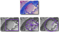
- A local scan assesses multiple areas of an image individually and determines the fractal dimension and other features for each local area.
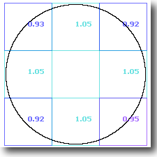
- The fractal dimension of the digitized circle shown here from a global scan, for instance, is 1.02, close to the theoretical value of 1.00, but parts of the digitized circle have different local dimensions (note that the value depends on the size of the samples)
- FracLac can be set to display graphically the variation with local scans (e.g., using text or colours).
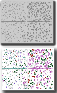
- In the image of cells shown here, for instance, the bottom portion shows each particle scanned separately with a local dimension determined as indicated by the colour coding. The fractal dimension for the entire image, shown in the top portion, in contrast, would be a global dimension.
global scan
Local Connected Fractal Dimension Scan
Random Mass Scan
Sub Scan Analysis
Particle Analyzer Scan
- Scan (Block Scan)
- Block Scan
- Block Analysis
- Block Texture
- Block
- An optional setting in box counting that forces the scanning area to be a square, with each grid calibre in a series limited to a multiple of the largest calibre.
- Block scans are appropriate for texture analysis, such as with grayscale images, where there is no contour separating the area of interest from the rest of the image.
- Scan (Fixed Grid)
- nonoverlapping
- nonoverlapping scan
- fixed scan
- fixed grid scan
- regular box count scan
- box counting using a series of grids of different calibre in a regular, exclusive array
- the grid does not change position while all the boxes are checked for pixels, as shown below
- the scan FracLac uses for a Standard Box Count
- contrasts with overlapping scanning
overlapping scan
Multifractal Scans
comparison of overlapping and nonoverlapping images
- Scan (Sliding Box)
- overlapping
- overlapping scan
- sliding scan
- sliding grid scan
- sliding box scan
- sliding box lacunarity scan
- gliding box scan
- box counting where one box size slides over an image moving each time by a predetermined distance and pixels it falls on are counted after each slide, until the entire image or roi is scanned once at each size in a series of sizes
- the type of scan used for calculating sliding box lacunarity
- contrasts with nonoverlapping scanning

Sliding Box Lacunarity Scan
grid position
overlapping scan
sliding box lacunarity
comparison of overlapping and nonoverlapping images
What is Lacunarity?
- Grayscale Scan
- Gray
- Average Intensity
- Average Pixel Intensity
- Grayscale DB
- Grayscale DM
- Non-binary
-
Grayscale images are one of two types of image FracLac analyzes (the other is binary). FracLac finds fractal dimensions and lacunarity for grayscale images in global and local scans.
Options for Grayscale Scans
To select grayscale scans, set the "Type of Image" to Grayscale when setting up a scan (e.g., see Box Counting). After you select grayscale, a dialog appears asking you to select a type of scan from 3 options. Note that they are all based on the "Differential Method". Click the links below to learn what they mean. NB: When doing a grayscale analysis of an image for texture, you may want to select the option for block scanning.Types of Fractal Dimension Reported for Grayscale Images
FracLac reports 3 basic types of fractal dimension for grayscale scans.All Grayscale Pixels are Meaningful
 Whereas pixels in a binary image can have 1 of 2 possible values—either background or non-background—pixels in grayscale images can have 1 of many values, where there is no guaranteed to be meaningless "background" pixel value. This is an important difference that defines the sorts of
analysis grayscale images are generally better suited for (e.g., texture analysis). (Note for now, but read later, that FracLac can be told to ignore parts of a grayscale image.)
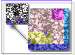
The picture shown here illustrates the general idea. It shows the same image of retinal vessels in binary and grayscale formats, with the same part amplified. No matter how small the sample,
in a binary box, pixels are either on or off, white or black; in the gray, there is no "off", all are "on" to a varying shade of gray.
If you have read the basics of box counting, you will already know that binarily behaved pixels bode well for binary scans, which count only the boxes that have meaningful pixels in them and can also count the number of meaningful pixels per box. And you may also have realized that grayscaling pixels are not so nice for such scans.
Whereas pixels in a binary image can have 1 of 2 possible values—either background or non-background—pixels in grayscale images can have 1 of many values, where there is no guaranteed to be meaningless "background" pixel value. This is an important difference that defines the sorts of
analysis grayscale images are generally better suited for (e.g., texture analysis). (Note for now, but read later, that FracLac can be told to ignore parts of a grayscale image.)
The picture shown here illustrates the general idea. It shows the same image of retinal vessels in binary and grayscale formats, with the same part amplified. No matter how small the sample,
in a binary box, pixels are either on or off, white or black; in the gray, there is no "off", all are "on" to a varying shade of gray.
If you have read the basics of box counting, you will already know that binarily behaved pixels bode well for binary scans, which count only the boxes that have meaningful pixels in them and can also count the number of meaningful pixels per box. And you may also have realized that grayscaling pixels are not so nice for such scans.
Indeed, if we analyzed grayscale images in the same way as binary, we would soon grow very, very bored with the results. The program would invariably tally every box it ever laid on a grayscale image, because all grayscale pixels, therefore all the pixels in every box, are meaningful. The mass approach would be as boring, because the program would invariably record that every box is full, learning nothing about the relative fullness of each. On the whole, since every count at any box size or scale (ε) would just give the number of boxes that fit across the entire image, and tell us that each box was filled, the single result of any log-log examination would always be the noble and beautiful but rather uninteresting and inaccurate integer dimensions.
Fortunately, FracLac does grayscale scans differently from binary, to find the meaning of the meaningful pixels. The data gathering box counting algorithms are the same, but the measuring mechanisms are not. It assumes grayscale images exist in a pseudo-3d space, where a pixel is not always either on or off but somewhere along a scale of on-ness and off-ness, that the world of computer graphics divides discretely from 0 (black) to 255 (white). This quantifiability can be thought of as a way to measure texture if we think in 3d and let the gray value (intensity) be a proxy for volume. Visualize this by picturing the screen as a 2d grid with i rows and j columns, and each pixel at i,j rising up as a little prism, or mountain, or spheroid, or mushroom cloud, or whatever you would like to use for your landscape, to the relative height defined by the intensity.
Intensity Differences
The methods by which FracLac turns these volumescapes into fractal dimensions are called Differential Box Counting Methods. They depend on something we will call I, for the difference in intensity, meaning the max − the min within some space like a box. There is some history in the fractal analysis literature behind using this range, but it is, nonetheless, arbitrary. In any sample of grayscale pixels, we could look, for instance, at the average intensity, maximum intensity, or distribution of intensity, but FracLac looks at I, the difference or range in intensity over all pixels in a box at a box size.To picture how FracLac does this, consider the image you surely made in your head when you read the previous paragraph about the texture of each pixel. Now, revisualize that scene, examining the image using, instead of individual pixels, boxes. Using boxes, you see one pillar or mushroom cloud rising not from each pixel, but from each box; change your scale of enquiry, your grid calibre, and you get, for each identically sized box in your new grid, a new shape rising up from the base of each box. Keep changing the grid size, and you keep getting one shape rising from every box, but the volume is changing. If you look at it with boxes the size of the image, you see but one large pillar or whatever shape you chose.
This gives us a way to find a fractal dimension (D) from a grayscale image. To help you understand that, let me give a quick summary: a box counting fractal dimension is a scaling rule that was inferred from the relationship between the number of parts (N) we count in some pattern and the relative size (f) of the measurer we use to count them. (f would be 1/3 if we multiplied the original pattern's size by 1/3 to get the measuring size). Read about it in the links later, but for now, know that the rule is N = f-D, and we solve for D using logs: -D = log N/log f. There is also a mass-related box-counting D, which relates N to the contents of the parts we measure, such as the sum or average of a feature measured at each box. And that is what happens with grayscale images and I. So, for purposes of knowing what we are talking about, here is how FracLac would identify the thing it would count and measure, the shape rising from a box, for some I at a box size ε and location i,j:
δIi,j,ε = Maximum Pixel Intensity(i,j,ε) − Minimum Pixel Intensity(i,j,ε)
You may have noticed the transformation in Eq. 2, where we add 1 to the actual range. To get ahead of ourselves for a moment, this prevents there from being 0 values in later calculations, which would crash our computers when we try to take logs. You can understand why this is ok if you realize that in the first place we are inferring something about geometry from pixel intensity rather than directly measuring it.
(Eq. 1) Ii,j,ε = δIi,j,ε
(Eq. 2) Ii,j,ε = 1 + δIi,j,εGray Fractal Dimension Types
As is the case with binary images, FracLac infers a scaling rule for a pattern, i.e., the D, by taking many measurements over many box sizes and approximating the log-log relationship from the slope of the regression line for the data. FracLac gathers for Iε the sum and the mean over all samples at each ε, and determines 3 different types of fractal dimension.- DB, from the log-log regression line of the sum of all Ii,j,ε vs ε
- DM, from the log-log regression line of the mean of all Ii,j,ε vs ε
- Dx̄, from an average cover over all grids then calculated as for DB
User Options for Grayscale Scans
There are 3 options the user can set in FracLac that affect the results of a grayscale analysis.Option 1: Differential
If the grayscale option is set to "Differential", then FracLac uses a method that is very similar to mass box counting. It approximates the slope of the log-log relationship between box size and I based on Eq. 2, and infers D from the regression line, as shown below: Iε = ∑ [1 + δIi,j,ε]
Nε = number of samples taken (e.g., boxes) at a size (or scale)
—Iε = Iε/Nε
DBgray = limε→0 ln(Iε)/ln (1/ε) = slope of the regression line.
DMgray = limε→0 ln(—Iε)/ln (1/ε) = slope of the regression line.Option 2: Differential Volume Variation
The 2d Variation is a variation of Option 1, that explicitly defines 3d volumes, Vi,j,ε, over a grayscale image. This is relevant to the discussion above in which we pondered mushroom clouds and the like. Basically, we imagine there is a 3d space for each pixel or box, for which Vi,j,ε will depend on the size and shape of the box and the range in intensity. FracLac approximates a volume from the size of the box2 × I: Vi,j,ε ∼ Ii,j,εε2 If the user has elected to use an oval sampling unit, FracLac calculates the base of this cylinder as a circle (e.g., areacircle = πr2).From this estimate of volume, FracLac calculates the log-log slope of Vεagainst ε, then uses a method based on the semi-variogram method (Mark and Aronson; Mandelbrot; Sarkur and Charduri), to calculate the fractal dimension. Basically, the method assumes that the slope is equivalent to twice something called the Hausdorff-Besicovitch dimension, and that D can be calculated as below: Vε= ∑Ii,j,εε2
S = limε→0(ln Vε/ln 1/ε) = slope of the regression line
DBgray = 3 - (S/2)Option 3: Differential Volume Variation Plus 1
Option 3 is nearly identical to Option 2. The only difference is that it uses Eq. 2 to calculate I, as shown below: Vi,j,ε ∼ (1 + δIi,j,ε)ε2
Vε= ∑(1 + δIi,j,ε)ε2
S = limε→0(ln Vε/ln 1/ε) = slope of the regression line
DBgray = 3 - (S/2)
- Connected Set
- Connected Set
 a set of pixels in a binary image that are all within the 8x8 local environment of the last pixel, starting with a seed pixel and repeatedly including all and only the pixels within the 8x8 environment of the last connected pixel and within some arbitrary distance of the seed
- the illustration shows the connected set within an 80 pixel area defined by the pink circle (i.e., the area extends for a 40 pixel radius from the centre), made for a picture of a part of my retina
- In FracLac, this is the basis for the local connected fractal dimension scan.
- Fractal Dimension (DLC Local Connected Fractal Dimension)
- LCFD or lcfd
- DLC
- Local Connected Fractal Dimension
- a type of fractal dimension calculated for binary images
- is found from a type of fractal analysis that uses pixel mass from concentrically placed sampling units, using the connected set at each pixel to produce a distribution of local variation in complexity.
- The LCFD is a local dimension, calculated for each pixel in the same general way that a DF for mass is calculated, using the slope of the log-log regression line for pixel mass against box size.
- A LCFD is distinguished from the global dimensions because there is a distribution of LCFDs for an image, which can be used to present local variation in complexity in data and graphics
- Mass
- Pixel Mass
- Pixels per Box
- Mean Pixels per Box
- ppb
- the number of foreground pixels in each box or sample, or the average over all boxes or samples, in a box count scan
- The mass or pixels per box (ppb) contrasts with the count of boxes that contained pixels in a usual box count.
- As shown in the illustration, the box count at the box size shown is 3 because 3 of the 4 boxes contain white pixels on a black background, but the mean ppb at that box size is 36.33, the total white pixels divided by the number of boxes that contained pixels (109 ÷ 3).
- pixel mass is used to calculate the mass fractal dimension, the local connected fractal dimension, and multifractal spectra in multifractal analysis
- pixel mass is also used to calculate lacunarity

- lacunarity
- Lac
- heterogeneity
- Λ λ
- gappiness and heterogeneity as a complement to complexity in describing digital images
- a measure of gaps and rotational and translational invariance in digital images
- the difference between λ and Λ is generally a matter of scale; there are many λs, one for each size of the sampling unit, whereas Λ is usually an average over all sizes used to sample an image
- See the Lacunarity page
Sliding Box Lacunarity
Types of Lacunarity in FracLac
Fλ
Eλ
Sλ
BPDλ
PΛ
How to Interpret Lacunarity Results in FracLac
- Lacunarity (foreground, λ)
- flac or Flac
- Fλ
- FΛ
- Foreground λ
- Foreground lacunarity
- Fg lacunarity
- F-lacunarity
- a type of lacunarity
- Fλ is distinguished from Eλ because it is based on only Foreground pixels (i.e., pixel masses)
- It is distinguished from Sλ because it is gathered during nonoverlapping rather than sliding grid box counting
- FBPDλ and EBPDλ are distinguished from Fλ because Fλ is calculated from the actual mass rather than a probability distribution
- is calculated from the relative variation in pixel mass with ε as well as over grid orientations
- Lacunarity (Sliding Box)
- Sliding Box Lacunarity
- SLAC or Sλ or SΛ
- Gliding Box Lacunarity
- Sliding box lacunarity is found similarly to the standard box counting value for lacunarity that FracLac reports, but is calculated based on data gathered using a different sampling method. Like fixed grid lacunarity, sliding box lacunarity depends on scale, so can be interpreted by looking at the log-log plot of Sλ vs ε.
sliding grid scan and Setting sliding box lacunarity options.
- SΛ = 1+ [σ/μ]2
- Lacunarity (prefactor)
- A measure of heterogeneity or translational invariance dependent on where a grid series is placed. It is reported in a standard scan with multiple locations, but, according to the equation below, PΛ=0 if there is only 1 sampling grid orientation, which reflects not that there is no variation but that no variation was assessed.
- This statistic uses the prefactor A from the scaling rule N=AεDB, where Ag = the prefactor calculated from the y-intercept for the ln-ln regression line for ε and count at grid g, and G = the number of sampling grid orientations.
Ag=1/(ey interceptg)
A = [G∑g=1Ag]⁄G
PΛ=G∑g=1[[{Ag/A}-1]2]/G
This value is reported in the results table as the mean y-intercept lacunarity for box counts and for pixel masses. The mean y-intercept is also recorded in the results table.
- the prefactor, A, is affected by the way data are gathered and especially by the lower limit of box sizes used
- Scans
- Type of Analysis
- Scan Types
- One of the types of scan available from the FracLac panel
- Local Connected Fractal Dimension Scan
- Multifractal Analysis
- Standard Box Count
- SubScans
- Sliding Box Lacunarity Analysis
- Mass vs Distance Analysis
- Scanning
- Running a Scan
- Scanning
- Analyzing
- For the user, this is clicking a button once options are set
- For FracLac, it involves:
- setting up an image and making some preliminary measurements (e.g., the convex hull),
- applying a sampling element (grids, boxes, ovals) to the prepared image and counting,
- calculating various parameters,
- displaying or saving the results.
- depends on the type of scan and the options the user selects
scan types
global scans; sub scans
nonoverlapping scan
overlapping scan
block scan
local connected dimension scan
- Fractal Dimension (Mean)
- Mean DB
- Average DB
- Mean DB
- Not to be confused with the average cover dimension, the average DB from multiple box counting scans, each delivering its own DB, based on a different orientation on the same image of the same series of grid calibres
- Calculated as:
- This value is reported in the results table for a Standard Box Count Scan as the Mean DB.
grid position
illustration of grid orientation
minimum cover
smoothing filter
Types of DB
- Smoothing Filter
- Smoothed Covering
- Smoothed DB
- Slope-corrected DB
- The smoothed data or its DB calculated from data transformed for periods of no change in the regression data.
- Horizontal slope periods arise spuriously in the plot of box size and count because the scaling factor is not known ahead of time. To illustrate, when FracLac uses a linear series of box sizes to maximally capture scaling in an image, after a point, as box size increases relative to image size, the number of boxes required to cover an image stays the same over a long interval of change in size. These plateaus affect the final slope and therefore the DB, but do not necessarily reflect actual features of complexity in a pattern.
- FracLac removes data points arising from such plateaus using 2 simple algorithms:
- Smoothed DB(biggest): a filter that shrinks the series by starting at the smallest box size and keeping only counts greater than the successor going from smallest to largest size. This filter obscures scaling and tends to bring the D closer to 1 when relatively large box sizes are used, but the effect depends on the image and the series of box sizes used.
- Smoothed DB(small): a filter that shrinks the series by starting at the largest size and keeping only counts smaller than the successor, which assumes that increases in count with increases in size should be ignored and that the smallest possible box for a given count holds density most efficiently. Thus, the smoothed DB(small), in essence, can be used to correct for box sizes that are too large (see discussion of limits in box counting options)
- The smoothing filter is especially useful in Multifractal Analysis
- Data from Smoothing Data Filters:
Box sizes in the data file
Box Size Series
Most Efficient Cover
- Minimum Cover
- Most Efficient Covering"
- Minimum Cover DB
- Most Efficient Cover DB
- The filtered dataset or its DB generated from box counting data over multiple grid positions using the least number of boxes required to cover the foreground pixels of an image
- For each grid size, the box count that was most efficient is selected from all of the grid positions tried. It is assumed to be most efficient inasmuch as it is the covering of all coverings tried that needed the least boxes to cover all of the pixels. If the number of grid positions is 1, this value is the same as the Mean DB.
- reported in the results table for a regular scan as the Minimum Cover DB.
- Minimum Cover Smoothed Filter
- Minimum Smoothed Covering
- Minimum cover smoothed DB
- Minimum cover slope-corrected DB
- The filtered data or its DB calculated using the filters for smoothing and minimum cover
- is only relevant if multiple grid positions are used; otherwise is the same as the smoothed values
- Maximum Cover Filter
- Maximum cover DB
- A filter that determines the least efficient covering attempted from box counting data by selecting from all grid positions the highest count for each ε and determining the DB using that dataset
- values provided by the maximum cover filter in the FracLac Results Table are for data checking only and are NOT representative DB values for an image
- Multifractal
- multifractal scan
- A multifractal is a fractal that scales with multiple scaling rules, as opposed to monofractals which scale with one scaling rule.
- A multifractal is expected to show different values for the generalized dimension or D(Q) for different values of Q, whereas a monofractal's values will be more similar in a
- A multifractal scan is a type of scan in FracLac that generates data and graphics describing multifractal scaling in digital images.
- Q
- Q
- q
- Q is an arbitrary exponent used in calculating the generalized dimension or D(Q) in multifractal analysis
- Q is significant to note in dimensional ordering
- Each value of Q is an exponent used to "amplify" the mean of the pixel mass distribution in calculating variables for multifractal spectra
- In multifractal analysis with FracLac, the maximum, minimum, and increment between Qs are set on the multifractal analysis options panel.
- Fractal Dimension (DQ Generalized Dimension)
- DQ
- Generalized Dimension
- D(Q) is called the generalized dimension.
- It is a measure used in multifractal analysis. It addresses how mass varies with ε (resolution or box size) in an image. In particular, it is a distortion of the mean (μ) of the probability distribution for pixels at some ε. To calculate it, μ is exaggerated by being raised to some arbitrary exponent, Q, then compared again to how this exaggeration varies with ε.
- D(Q) is used to make multifractal spectra.
- at Q=0, the generalized dimension is equal to the "capacity dimension" which is essentially equivalent to the box counting dimension; at Q=1 it is equal to the "information dimension", and at Q=2, to the "correlation dimension". In general, D(Q) is a decreasing function, sigmoidal around 0, where DQ=0≥ DQ=1≥ DQ=2≥.
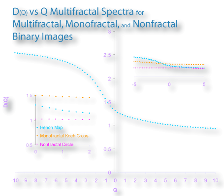 For multifractals, these values diverge but for monofractals and non-fractals, they converge. As illustrated in the image, in the spectrum from box couunting for a non-fractal of theoretical capacity dimension of 1.00, for instance, the slope is relatively unchanging especially for Q>0.
 - See multifractal spectra for a brief discussion of this topic
- Dimensional Order
- a general trend important in interpreting results in multifractal analysis
- a rule for the generalized dimension, where the Capacity Dimension ≥ the Information Dimension ≥ the Correlation Dimension or:
D(Q=0) ≥ D(Q=1) ≥ D(Q=2)
- a rule for the generalized dimension, where the Capacity Dimension ≥ the Information Dimension ≥ the Correlation Dimension or:
- Probability Distribution (Binned)
- BPD
- Binned Probability Distribution
- Probability Distribution
- BPDλ
- BPDλ
- BPDL or BPD
- Binned Probability Density Lacunarity
- A binned probability distribution of pixels per box from a box count.
See the BPD page for a detailed discussion.
- "BPDL" in the various results files means a type of lacunarity related to but distinguished from other λs because BPDL is calculated using the frequency of masses in a "bin" (i.e., a range from some minimum to a maximum) rather than actual masses of pixels per box
- The Dmass= the slope of the regression line for the ln μεBPD/ln ε
- IMPORTANT PRACTICAL TIP: FracLac does not use BPD by default, so if you would like it to use a BPD:
- Type a number > 0 for Number of Bins in the options panel for the scan you are doing
- Select whether or not to generate a file showing the probability distribution data by selecting Print Mass vs Frequency Distributions
- The "Frequency Distribution" option for a LCFD scan refers to the distribution of DFs by pixel over an image rather than pixel masses per ε as described here
- Prefactor
- The prefactor A from the scaling rule for fractal dimensions (DF):
N=AΕDF
A is calculated A=1/(ey intercept)from the y-intercept for the ln-ln regression line for S (size or ε, which represents Ε in the scaling rule,) and C (count, which is a proxy for N in the scaling rule above) from box counting, where m=slope and B = the number of box sizes or εs
y-intercept = [B∑b=1 LnCb−(m×B∑b=1 LnSb)]÷B
m=((B×B∑ b=1 LnSb×LnCb)−(B∑ b=1 LnSb×B∑ b=1 LnCb))
÷
((B×B∑b=1 LnS2)−B∑ b=1 LnSb×B∑ b=1 LnSb))
- Empty Boxes
- Image Count
- Empties
- ω
- Empty Boxes
- The empties count or ω or image count is arrived at by a rule that increments, for each box in a grid assessed on an image, either the box count or the empties count. The mass at each "empty" is 0, of course, but, as shown in the image below, when included in the mass calculations the empties count changes the mean and can affect lacunarity and the mass dimension. When included with the count, this measure is used to assess how an image was divided up.
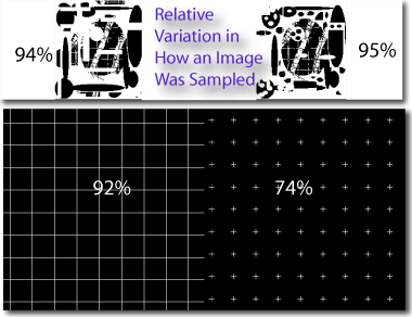
- Foreground Count CV/Image Count CV
- A ratio that uses the entire space that was sampled into account, including empty boxes, to assess the sampling of an image - how it was divided up at different times. Basically, it is the ratio of how the number of boxes it took to cover the foreground pixels varied with the size of the boxes, compared to how the total number of boxes the entire image was broken into varied with the size of the boxes.
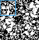
- It is best understood with an example. Each of the pairs shown in the montage here has identical sizes and numbers of pixels with similarly regular or irregular patterns (one in each pair was actually made by rearranging pixels from the other). The two irregular patterns on the top have very similar ratios of 94% and 95%; the two regular patterns on the bottom, however, have ratios of 92% and 74%, reflecting that the top two are divided very similarly in a box count at all εs, but the bottom two diverge (this is primarily as ε gets small, where the grid pattern breaks down more evenly and the cross pattern more clustered).
- For box counts, the value reported in the Results file is the ratio of the mean CV over all grids for box counts out of total counts.
- Lacunarity (empties ω)
- Empties Lacunarity
- Eλ
- Unoccupied λ
- In FracLac, you will see Eλ, Fλ, BPDλ, and Sλ. Eλ is a type of pixel mass-based lacunarity that takes into consideration the empty boxes sampled in a box count.
- Is used along with the original mass counts in Binned Probabilities and regular lacunarity calculations to find an adjusted CV2 or Eλ
- To calculate Eλ and EBPDλ, the number of empties is added to the mass counted, then Eλ is determined using the same method as λ (see how to calculate λ). This in effect scales λ according to the gaps that become resolvable in the space occupied within the bounding box of the foreground pixels of an image as ε changes. The ratio of σ (the standard deviation) to μ (the mean) used to calculate lacunarity changes as these both decrease, but the ultimate effect as Eλ=(Eσ/Eμ)2 depends on ε and the image.
- convex hull
- hull
- polygon
- a connected series of straight segments convexly enclosing all of the foreground pixels of a binary image, found for the image using the bounding box as oriented
- the hull can be contrasted with the bounding circle and bounding box
- you can calculate the convex hull without doing a box count by selecting the option to do a hull but setting the number of grid orientations to 0.See more on the Discussion and Results pages.
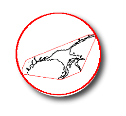
- Circle
- Bounding circle
- Enclosing Circle
- the smallest circle enclosing all of the foreground pixels of a binary image, calculated using the maximum span across or else the three points defining the smallest circle around the convex hull.
- When doing a Standard Box Count, you can calculate the bounding circle without doing a box count by selecting to do circularity but setting the number of grid locations to 0.See more on the Discussion and Results pages.
- Bounding Box
- bounding rectangle
- image dimension
- bounding box
- the smallest rectangle oriented with the x,y axes of the computer screen and enclosing the foreground pixels of a digital image, as illustrated here
- the bounding box is used for determining the relative size of the largest box in calculating the series of sampling sizes and determining the scale for box counting
- the bounding box is also important in determining the size of the square in block scans

- Morphometrics (other)
- radii; circularity; perimeter; span ratio; density; diameter; height; width
- hull metrics
- metrics provided in the hull and circle analysis; for explanations of these values, see the HC results file
- these are supplementary to fractal analysis
- metrics based on the convex hull and bounding circle
- For an introduction, see Other morphometrics
- Binary File
- Binary Contour
- Black and White
- one of the two types of inputs FracLac works on: binary or grayscale digital images.
- strictly speaking, a binary image is one that has only 2 possible values for its pixels.
However, by convention and in FracLac, binary means black and white (i.e., digital images having no other pixel values than 0 and 255).
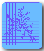
Hover over the image of a diffusion limited aggregate to switch between blue & purple binary and black & white binary. But know that you would have to convert your image to black and white binary (e.g., using ImageJ's threshold function) to process it with FracLac.
- A grayscale image may be converted to binary by thresholding (e.g., making all pixels below some value black and all above or equal to that value white), although FracLac can also scan grayscale images assessing different information than in binary images.
- Pixel Value
- pixel
- pixel value
- the colour or the intensity of the pixels in a digital image that are relevant to a particular type of scan and about which information is gathered
- foreground pixels
- foreground
- meaningful pixels
- F
- nonbackground pixels
- information pixels
- the pixel colour deemed to be "of interest" in box counting of binary images
- in a binary scan (but not grayscale) one colour of pixels is considered to contain meaningful information, so that all other pixels are background or noise (see also empties)
- in a standard box count scan, foreground pixels are the pixels that were deemed "foreground" by the program and that were included in the scanned part of the image.
- foreground is either black or white in a binary scan; which colour is chosen can be fixed by the user or determined by the program, depending on the user's settings
- "F" is prefixed on various values returned by FracLac (e.g., Fλ) to distinguish these from "E"; "F" means that the value was calculated based on foreground pixels and not including the empties count
- all pixels are considered foreground in a grayscale scan, and are assessed by intensity
- NOTE: in LCFD scans, the pixels of interest are determined differently, using the connected set
Explanation of how to set the colours in FracLac
background pixels
- Background
- background pixels
- non-meaningful pixels
- background
- nonforeground pixels
- non-foreground pixels
- in binary scans in FracLac, the pixel colour deemed to be not of interest, as contrasted with foreground pixels
- black or else white in a binary scan
- in a standard box count scan, background pixels are the pixels that were deemed "background" in the options panel; that is, the program can determine which colour is more prevalent and call that background or the user can choose which colour to consider background.
- background in grayscale images is a different notion than in binary images; there is no single "background" pixel colour in a grayscale image, but FracLac sets a background colour (green) that it ignores to make it possible to select regions of interest (Rois) in grayscale scans
- outside of the context of scanning with FracLac, background has another meaning for grayscale images, and in this regard, prior to scanning, one can process grayscale images to remove background using ImageJ's background subtraction function. This is part of image preparation.
Explanation of how to set the colours in FracLac
foreground pixels
- Image Size
- Image Size
- Image Dimension
-
For binary images, one of the dimensions of the bounding rectangle containing the foreground pixels of an image or roi
- For grayscale images, one of the dimensions of the bounding rectangle for the entire image or roi
- Whether the larger or the smaller of the width and height is used for calculating maximum box size depends on the user's selection
- For grayscale images, one of the dimensions of the bounding rectangle for the entire image or roi
- data file
- datafile
- raw data
- a file of data not included in the summary file
- not made by default; is generated only if selected on the options panel(click thumbnail for more)
- see data file page
- Standard Error
- Standard Error (SE)
- The standard error for the regression line.
- This value appears beside each fractal dimension in the results table. This is a test of the validity of the regression line from which the DB is calculated.
- The SE, equivalent to a common standard deviation in the distribution of count values at all box sizes, is generally interpreted as a measure of how accurately a proposed relationship predicts detail from scale based on the data.
- Correlation Coefficient
- r2
- The coefficient of determination, r2, for a regression line such as those showing the relationship between the log of count and size in calculating the DB.
- This value appears beside each fractal dimension in the results table as a test of the regression line. Strictly speaking, a value of 1.0 shows perfect correlation in the data; in fractal analysis, however, such correlation does not reflect correlation with theoretical values. Rather, this statistic describes the extent to which the relationship between the logarithms of scale and detail is linear. An r2 of 0.95, for example, indicates that 95% of the variation in detail (measured as the logarithm of box count) is accounted for by corresponding linear variation in scale (measured as the logarithm of box size) according to a proposed power law. This measure does not, however, predict consistent scaling. The data may be strongly positively correlated despite that the regression line poorly represents the overall scaling in an image.
- Coefficient of Variation
- CV
- CV2
- Coefficient of Variation
- σ/μ, (σ/μ)2
- a measure of relative variation in data, as the ratio of the the standard deviation (σ) to the mean (μ); it is sometimes squared or multiplied by 100
- the CV for pixel mass is used to determine lacunarity
- the Coefficient of Variation over all locations in box counting measures variation in the DB as it depends on the orientation of the series of grids. This can be used along with lacunarity to measure heterogeneity and dependence of the DB on orientation.